Packet Core Expertise
The EPC is the latest evolution of the 3GPP core network architecture.
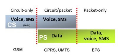
In GSM, the architecture relies on circuit-switching (CS). This means that circuits are established between the calling and called parties throughout the telecommunication network (radio, core network of the mobile operator, fixed network). This circuit-switching mode can be seen as an evolution of the "two cans and a string". In GSM, all services are transported over circuit-switches telephony principally, but short messages (SMS) and some data is also seen.
In GPRS, packet-switching (PS) is added to the circuit-switching. With this technology, data is transported in packets without the establishment of dedicated circuits. This offers more flexibility and efficiency. In GPRS, the circuits still transport voice and SMS (in most cases). Therefore, the core network is composed of two domains: circuit and packet.
In UMTS (3G), this dual-domain concept is kept on the core network side. Some network elements have evolved but the concept remains very similar.
When designing the evolution of the 3G system, the 3GPP community decided to use IP (Internet Protocol) as the key protocol to transport all services. It was therefore agreed that the EPC would not have a circuit-switched domain anymore and that the EPC should be an evolution of the packet-switched architecture used in GPRS/UMTS. This decision had consequences on the architecture itself but also on the way that the services were provided. Traditional use of circuits to carry voice and short messages needed to be replaced by IP-based solutions in the long term.

Circut and Packet Domains

Architecture of the EPC
EPC was first introduced by 3GPP in Release 8 of the standard.
It was decided to have a "flat architecture". The idea is to handle the payload (the data traffic) efficiently from performance and costs perspective. Few network nodes are involved in the handling of the traffic and protocol conversion is avoided.
It was also decided to separate the user data (also known as the user plane) and the signalling (also know as the control plane) to make the scaling independent. Thanks to this functional split, the operators can dimension and adapt their network easily.

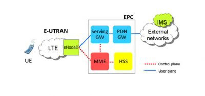
Figure shows a very basic architecture of the EPS when the User Equipment (UE) is connected to the EPC over E-UTRAN (LTE access network). The Evolved NodeB (eNodeB) is the base station for LTE radio. In this figure, the EPC is composed of four network elements: the Serving Gateway (Serving GW), the PDN Gateway (PDN GW), the MME and the HSS. The EPC is connected to the external networks, which can include the IP Multimedia Core Network Subsystem (IMS).

HSS
Basically, the HSS (for Home Subscriber Server) is a database that contains user-related and subscriber-related information. It also provides support functions in mobility management, call and session setup, user authentication and access authorization. It is based on the pre-3GPP Release 4 - Home Location Register (HLR) and Authentication Centre (AuC).
Serving GW
The gateways (Serving GW and PDN GW) deal with the user plane. They transport the IP data traffic between the User Equipment (UE) and the external networks. The Serving GW is the point of interconnect between the radio-side and the EPC. As its name indicates, this gateway serves the UE by routing the incoming and outgoing IP packets.
It is the anchor point for the intra-LTE mobility (i.e. in case of handover between eNodeBs) and between LTE and other 3GPP accesses.
It is logically connected to the other gateway, the PDN GW.
PDN GW
The PDN GW is the point of interconnect between the EPC and the external IP networks. These networks are called PDN (Packet Data Network), hence the name. The PDN GW routes packets to and from the PDNs.
The PDN GW also performs various functions such as IP address / IP prefix allocation or policy control and charging.
3GPP specifies these gateways independently but in practice they may be combined in a single "box" by network vendors.
MME
The MME (for Mobility Management Entity) deals with the control plane. It handles the signalling related to mobility and security for E-UTRAN access.
The MME is responsible for the tracking and the paging of UE in idle-mode. It is the termination point of the Non-Access Stratum (NAS).
Support of multiple access technologies
As seen in EPS Architecture, the UE can reach the EPC using E-UTRAN however this is not the only access technology supported. 3GPP specified support of multiple access technologies and also the handover between these accesses. The idea was to bring convergence using a unique core network providing various IP-based services over multiple access technologies.
Existing 3GPP radio access networks are supported. 3GPP specifications define how the interworking is achieved between an E-UTRAN (LTE and LTE-Advanced), GERAN (radio access network of GSM/GPRS) and UTRAN (radio access network of UMTS-based technologies WCDMA and HSPA).
The EPS also allows non-3GPP technologies to interconnect the UE and the EPC. Non-3GPP means that these accesses were not specified in the 3GPP. These technologies includes e.g. WiMAX, cdma2000®, WLAN or fixed networks.
Non-3GPP accesses can be split into two categories: the "trusted" ones and the "untrusted":
Trusted non-3GPP accesses can interact directly with the EPC.
Untrusted non-3GPP accesses interwork with the EPC via a network entity called the ePDG (for Evolved Packet Data Gateway). The main role of the ePDG is to provide security mechanisms such as IPsec tunnelling of connections with the UE over an untrusted non-3GPP access.
3GPP does not specify which non-3GPP technologies should be considered trusted or untrusted. This decision is made by the operator