IP & Transport Network Services
This paper proposes a next-generation IP core transport network architecture that ful- ly utilizes the features of a photonic network. To cope with the IP traffic trends and users’ demands for Quality of Service (QoS), we propose a virtual router network par- adigm to make the public network operate and look like a single virtual router. Also, we present a traffic-engineering scheme and a network protection scheme for ensur- ing a high utilization of network resources and a high reliability.
1. Introduction
Because of the Internet explosion, the de- mand for transmission capacity is increasing exponentially at a higher rate than can be accom- modated by Moore’s law. The next-generation IP core network must be able to sustain this increase. In this paper, an “IP core network”1) means a net- work that can support the IP transfer capability defined in the ITU-T IP between access networks and an “IP core transport network” means a net- work that can transport IP traffic with a functionality below layer 2.
Among the new trends in IP traffic, the con- tinuous increase in traffic volume and the increasing demand for Quality of Service (QoS) should be considered for the next-generation IP core transport network. The transmission capac- ity of optical fiber links supported by the use of dense wavelength division multiplexing (WDM) technology has overtaken the increase in traffic volume and capacity demand. However, even if the transmission capacity is sufficient for the de- mand, the node implementation required for a CPU processing ability that can handle huge vol- umes of traffic cannot be achieved simply through the progress of semiconductor technology.
Furthermore, the demand for QoS has been increasing due to a variety of information process- ing systems which include mission critical applications, changes in the contents delivered by the Internet, and guaranteed communications bandwidth and availability. If we try to handle all the IP traffic at the IP layer or a higher layer to support QoS, the processing at the nodes will become crucial problems. Therefore, part of the traffic should be handled below the IP layer and the processing load in the nodes should be reduced. One way to achieve these goals is to combine the dynamic label path set-up concept used in multi- protocol label switching (MPLS) together with traffic engineering technology.
A fundamental change in IP core transport network architecture is necessary to solve the pos- sible node processing bottleneck problem. Our proposal is to make a network paradigm shift to- ward a virtual-router view network by fully utilizing the features of photonic network tech- nology. Details are given in the following sections. We also explain that dynamic traffic engi- neering and network protection technology is another key technology for providing guaranteed service, resilience to sudden traffic changes, and economical preparation of a protection path for quick recovery.
2. Virtual-router view network based on photonic technology
Virtual-router view network
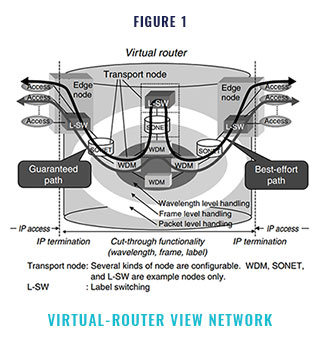
Figure 1 shows the virtual-router view net- work which we propose as a next-generation network paradigm. Our approach is to make the public network operate and appear like a single router. Most of the intelligence is moved to the edge node, and the core consists of a simple, very high capacity data transport mechanism. In- coming IP packets are terminated at the ingress node, then paths assigned between the ingress and egress nodes are used for transporting IP pack- ets. Here, “IP packet termination” means that the IP layer processing required for processor process- ing has been completed. The internal transfer of IP packets in the virtual-router view network is done based on the path and efficient switching technologies such as layer 1 wavelength switch- ing, SONET-like (Synchronous Optical Network) jumbo frame switching, and layer 2 label switch- ing. These switching technologies are described in Section 2.2. At the egress edge node, IP pack- ets are terminated again and sent out to the access line. This architecture releases the IP data from the hop-by-hop processing required for the cur- rent router networks that execute IP layer processing in each router/node. The best-effort path and the guaranteed path are prepared, and and each IP packet is properly assigned to the appropriate path at the edge node. The guaranteed path may be provided by using different transport mechanisms, for example, asynchronous transfer mode (ATM) and SONET and/or their composite transmission mode. A WDM-based photonic net- work enables this type of configuration. WDM systems provide wavelength transparency; that is, they provide independence between wave- lengths. This means that different transmission modes, different bit rates, and different QoS class paths can be realized in a WDM system by as- signing multiple wavelengths to a single fiber. The schematic diagram of the network is shown in Figure 2.
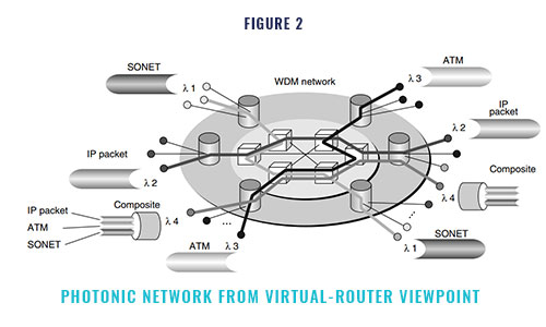
In addition to the wavelength level, paths are also configured according to the SONET paths, the labeled paths of MPLS, and other levels.
Node configuration example
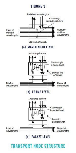
Figure 3 shows a candidate IP core transport node structure within the virtual-router view network
A transport node can provide node cut- through at different traffic granularities Node cut-through functionality means that unnecessary processing passes through nodes. For example, node cut through at the wavelength level means that only the required wavelengths are added or dropped at the designated node and the other wavelengths pass through the node. Similarly, cut-through at the frame level means that pay- load information in only the designated frames is added or dropped at the designated node and the other information is passed through. SONET add/ drop multiplexing (ADM) or cross-connecting (XC) can provide this functionality. In some cases, a jumbo frame level such as a digital wrapper frame, which can encapsulate a Gigabit Ether- net, ATM, and/or SONET, can also be applied. In addition, node cut-through will be done at the layer 2 packet level. IP packets can be encapsu- lated with a fixed length label, which is used as a switching label between the ingress and egress edge node/routers. This type of labeled packet can be dropped or added at the designated node and passed through the intermediate nodes. The label switched path (LSP) in MPLS discussed in Section 4 can be configured by using node cut through at the layer 2 packet level.
Because of their node cut-through function- ality, the transport nodes described above need to perform less packet processing and therefore do not need so much packet processing power. Basi- cally, nodes except edge nodes and edge routers do not need to perform IP layer processing and only need to handle lower layers such as the wave- length layer
The transport node in the virtual-router view network can be configured as a variety of struc- tures. Some nodes can only handle wavelengths, and some have wavelength add/drop functions and layer 2 level packet handling functions without frame level handling. In addition, some trans- port nodes may have a combination of router functions which handle IP layer processing. The label switching router (LSR) discussed later is also a kind of transport node which focuses on layer 2 packet level functionality
Virtual-router view networking by wavelength paths
Node cut-through according to wavelength is a key technique for the IP core transport network because it simplifies the IP core transport network and therefore makes it possible to build economi- cal networks. However, the networking scale depends on the size of the logical full-mesh net- work that can be configured using the available number of wavelengths. Here, a “logical full mesh” means a mesh in which each node has a direct logical path to all the other nodes in the network: in other words, each node has independent wave- length paths to all the other nodes. By using the WDM feature, multiple independent optical wave- length paths can be provided on a fiber.
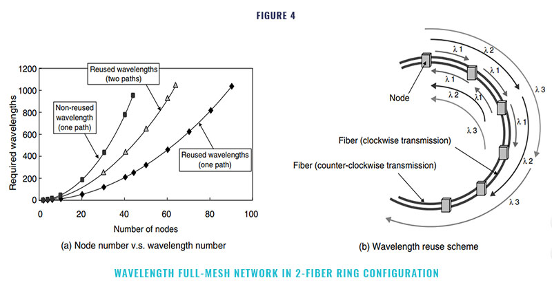
A figure of 256 optical wavelength paths is within reach, and a target of 1024 has already been set. In ad- dition, optical add drop and cross connection functions, which route optical wavelength paths according to their wavelengths, have became available. These functions make it feasible to provide multiple wavelength paths on a fiber and to drop only the necessary optical wavelength path at the designated node. Figure 4 (a) shows the results of calculating the number of nodes which can be accommodated in an example 2-fiber ring network with a logical full-mesh structure as a function of the available number of wavelengths. The calculation assumes that each fiber is uni- directional; that is, one fiber is used for clockwise transmission and the other is used for counter- clockwise transmission. In the wavelength reuse scheme shown in Figure 4 (b), different wave- lengths between nodes are applied as different paths. Figure 4 (a) also shows the case when two wavelength paths are provided between nodes, one for best effort and the other for guaranteed com- munication.
When the target of 1024 wavelengths per fiber is reached in the near future, even a simple 2-fiber ring structure can be used to construct a full-mesh network having 90 nodes when there is one path or 64 nodes when there are two paths. If more scalability is required in the number of nodes and paths between nodes, a space division technique using more fibers or a hierarchical net- work configuration can be used. Especially, if the network configuration is not limited to a ring net- work, then point-to-point paths carrying a large number of wavelengths can be installed between designated nodes.
If there are insufficient wavelength paths in the network, each wavelength in a virtual-router view network can be shared among multiple paths, each of which can be formed at the jumbo frame base level and/or the labeled packet flow level. If necessary, transport nodes can provide cut- through functionality at different levels, for example, at the wavelength, frame, or labeled packet level. Therefore, a logical full-mesh con- figuration of wavelength paths associated with higher level paths is a technically realistic solu- tion. In addition, such a configuration will simplify the network, make the node implementation fea- sible, and is potentially economical.
Effect of virtual router configuration
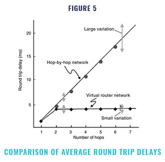
Some of the main issues in current IP net- works are the length and variation of the end-to-end delay when transporting IP packets. Taking the necessary measures to compensate for this delay, for example, in a voice over IP applica- tion, considerably complicates implementation. Therefore, increases in the delay length and vari- ation should be avoided as much as possible, even when the network becomes larger. To examine the possible improvement in delay performance obtained with a virtual-router view network, we carried out a preliminary study by computer sim- ulation.
Figure 5 shows the result of simulating the round trip delay of a PING command. For the current hop-by-hop network, when the number of hops is increased there is a linear increase in the average round trip delay and the variation of this delay becomes large. With the virtual router net- work, owing to the cut-through effect, the round trip delay stays small and the variation is also small, although the delay increases by two hops due to the IP layer processing done at the input and output of the virtual router network.
3. Issues for high-efficiency and high-reliability packet transportation in the virtual- router view network
The Internet is a huge database of multime- dia content and is beginning to provide not only non-real-time data services but also real-time ser- vices such as audio and video. However, as the Internet grows, network congestion is becoming a serious problem.
The main problem is that the traditional routing protocol does not consider the network condition when selecting a transportation route for an IP packet and, therefore, it can concentrate traffic on a specific route. Since traditional rout- ing protocols such as open shortest path first (OSPF) selects the single shortest route (or minimum-cost route), traffic flows tend to concen- trate on a specific route in the network while the other links are lightly loaded. This problem of congestion and the low efficiency of network resources makes it more expensive for network operators such as Internet service providers (ISPs) to install network facilities. We will discuss this point in Section 4.
Another important issue is how to construct a reliable core network. Recent improvements in transmission technology have enabled large in- creases in the capacities of transmission systems. However, considering that the IP network will become one of the main information infrastruc- tures, a fault in such a transmission system could cause a serious social problem. This point is dis- cussed in Section 5.
4. Traffic engineering
Traffic engineering system
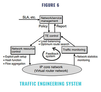
Traffic engineering (TE) has been presented as a technology that can solve this problem regarding the seriousness of faults. TE automatically optimizes network resources. It also makes it possible to avoid congestion, recover from congestion when it occurs, and achieve a high utilization of the network resources by load balancing.
The objective of TE is to dynamically opti- mize network resource allocation so that the performance objectives of the application service (e.g., bandwidth and delay) and those of the net- work (e.g., link utilization) are met. The system that performs these tasks is called the TE sys- tem.
The TE system consists of the TE control, network resource control, and traffic monitoring (Figure 6). The input of the system is the service profile or service level agreement (SLA), which describes the performance objectives of the user application or the network and the performance objectives set in the TE control. The TE control executes optimization control by using the func- tions of the network resource control based on the service profile. The load balancing algorithm and optimal route search algorithm are executed in the TE control. Network resource control is a set of functions for traffic handling, for example, an explicit path setting function and flow distribu- tion functions for load balancing (described later in Section 4.2). The TE control decides which con- trol is necessary based on the information about the network condition acquired by the traffic mon- itoring. Then, according to the result, the TE control executes optimization by reallocating the network resources. Thus, the TE system forms a feedback loop.
Developed technique
Next, we describe a new technique we have developed as the first step toward autonomous optimization of IP network resources. This technique can be realized by extending the tech- niques of MPLS, which is a switching scheme for providing a fast Internet backbone using a fixed- length label in a packet. A router capable of MPLS is called a “label switching router (LSR),” and a path set by MPLS is called a “label switched path (LSP).” The concept of using a layer 2 path such as an LSP between the ingress and egress edge nodes in a virtual router network has been ap- plied to the MPLS. That is, a new layer path rather than a usual layer 3 route can be established by an operation policy
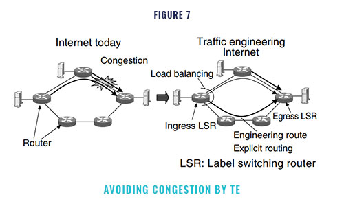
Our TE system searches for the optimal routes automatically, sets explicit paths, and bal- ances loads by splitting the IP flows into multiple paths. In this way, the system ensures a high uti- lization of network resources and improves the service quality by avoiding congestion (Figure 7). The key functions for implementing the TE sys- tem in an IP network are as follows :
- Flow aggregation : This function aggregates IP flows based on attributes such as the source address and desti- nation address. The forwarding equivalent class (FEC) concept of MPLS2) can perform this function.
- Explicit path setting : This function sets a path by explicitly speci- fying each node (LSR) in the path. Using MPLS, the path (LSP) is set by a signaling protocol such as the resource reservation protocol (RSVP)- LSP-Tunnel10) or the constraint routed label dis- tribution protocol (CR-LDP).
- Load balancing : This function distributes IP flows having the same destination among multiple paths in the network. The distribution is done in units of aggregated IP flows. One way to implement this function is to decide the path of an IP flow accord- ing to the hash value calculated from the packet’s attribute. To balance the load of each path, the network resource control adjusts the hash bound- aries which map the hash value to the path that the flow traverses based on the information of the links’ load in the paths.
- Engineering route search : This function searches for an alternative route for load balancing. We call this route the “engineering route.” The ingress LSR shown in Figure 7 calculates the engineering route. The engineering route is not a minimum-cost route decided by an existing routing protocol such as OSPF, but is a route that has the maximum avail- able bandwidth. The algorithm for this function is realized by extending a shortest path first (SPF) algorithm, for example, the Dijkstra algorithm
- Traffic statistics monitoring : This function collects network statistics such as the link utilization and packet loss ratio. Each router in the network obtains the statistics by monitoring the links’ traffic and reports the sta- tistics to the TE control routers. Ingress LSRs that execute TE control can learn the overall net- work condition and load condition of LSPs and can use the statistics to calculate all link costs when searching for an engineering route. This function is realized, for example, by periodic flooding of the OSPF opaque link state advertisement (LSA) con- taining the statistics of each router.
Working example of traffic engineering
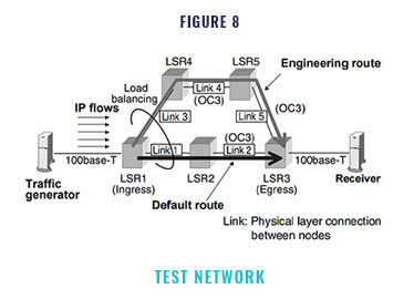
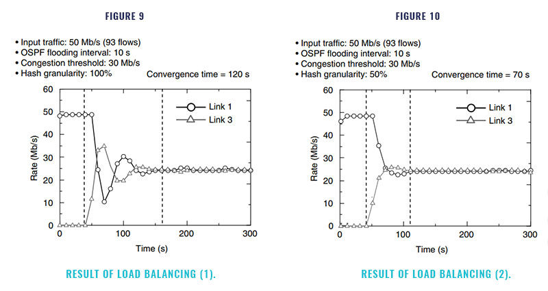
We developed the TE system software and evaluated its performance. We configured the network as shown in Figure 8 and then confirmed the load balancing behavior and evaluated the relation between the amount of traffic movement and the convergence time. We used a hash func- tion as a load balancing algorithm and prepared a hash granularity value as a parameter for mov- ing the hash boundaries.
The results are shown in Figures 9 and 10. In these figures, the vertical axis shows the utili- zation of link 1 of the default route and link 3 of the engineering route. The routers flood the traf- fic state of the links every 10 seconds. Therefore, the edge node (LSR1) can recognize if the default route is congested after a few seconds. Then, when the edge router finds an alternative route, it es- tablishes a new LSP along the engineering route and then starts to move traffic from the default route to the engineering route. The movement of traffic among routes has been completed if the traffic of both routes is equal. Thus, the conges- tion of the lower route can be resolved
When the hash granularity value is large (Figure 9), since the instantaneous amount of traf- fic movement is large, the link rate oscillates until convergence. This oscillation can be avoided and the convergence time reduced by setting the ap- propriate hash granularity value (Figure 10).
5. Network protection
Another important issue is how to construct a fault tolerant IP core network for the informa- tion infrastructure, because a failure in a large-capacity transmission system could cause a serious problem. Our proposed network protec- tion scheme is described below.
The protection requirements are as follows:
- Quick protection
- Efficient bandwidth usage for the protection path
If the service quality for real-time services such as voice call is maintained even when a fault occurs, a quick fault recovery, for example, less than 100 ms, is required. To realize quick protec- tion, two basic strategies are adopted. The first is to pre-plan the protection path. If the protec- tion path is searched for after a fault occurs, it will take a long time to recover. Therefore, the protection path should be determined when the working paths are determined. The second strat- egy is to segment the network domain for quick protection. If a protection domain is large, it will take a long time to report a fault to each node. Therefore, protection domains should be segment- ed so that it takes no more than, for example, 30 ms to report a fault to an edge node (Figure 11).
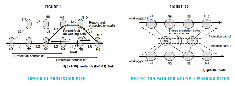
If protection paths are established indepen- dently, a large amount of bandwidth will have to be reserved, which is inefficient. However, the possibility of faults happening simultaneously in two or more locations is very small. Therefore, the bandwidth of the protection path can be shared among multiple working paths so that the re- quired bandwidth can be reserved efficiently. Figure 12 shows an example of sharing the band- width among working paths 1 and 2. In this way, more than 10% of bandwidth for protection can be saved.
6. Conclusion
In this paper, we proposed a next-generation IP core transport network architecture that fully utilizes the capabilities of the photonic network and is based on the virtual router network para- digm. We described the node bottleneck resolution architecture, wavelength path routing capability for a full-mesh network, traffic engineering scheme for efficient network resource utilization, and network protection scheme of our proposal. The elements of our proposal can meet the ever increasing IP traffic trends and user-demand for Quality of Service
